xzcChinese
Inquiry
Form loading...

What Is a DDC Panel in BMS?

Modern buildings depend on control systems that occupants rarely see. A Ddc Panel Bms connects sensors, controllers, actuators, and software across heating, ventilation, air conditioning, lighting, and energy systems. It turns temperature readings, airflow signals, and occupancy data into practical control decisions. In a plant room, this may mean opening a valve, starting a pump, or adjusting a supply-air setpoint within seconds.

The need is measurable. The International Energy Agency reports that buildings account for about 30% of global final energy consumption and roughly 26% of energy-related emissions. The UNEP Global Status Report for Buildings and Construction presents similar concerns about inefficient building operations. These figures make control quality more than a technical preference. A properly designed DDC panel can support stable comfort, lower operating waste, alarm management, and clearer maintenance records. ASHRAE Standard 135, BACnet, provides a widely recognized framework for communication between building automation devices.

Details matter.

A DDC panel is not automatically efficient because it contains a modern controller. Poor sensor placement, incorrect sequences, weak network design, or neglected calibration can undermine the entire system. That point is easy to miss. Industry guidance, including ASHRAE standards and U.S. Department of Energy building-controls research, emphasizes commissioning, trend analysis, and operator involvement. This article explains what a Ddc Panel Bms is, how its main components work, and where design decisions affect performance. Some projects still treat the panel as a box of hardware. That assumption deserves careful reconsideration. A reliable panel should function as the building’s measurable control nerve center, not merely as an electrical enclosure.

What Is a DDC Panel in BMS?

Definition and Purpose of a DDC Panel in BMS

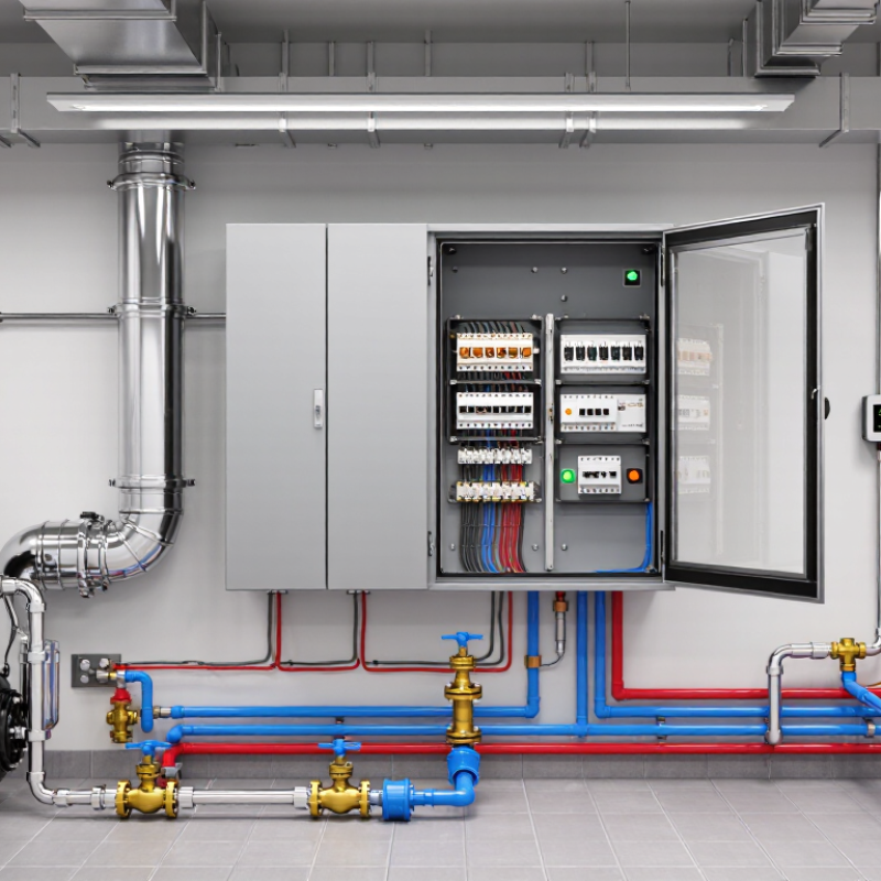
A DDC panel is the local control cabinet within a building management system. DDC means direct digital control. It receives signals from temperature, humidity, pressure, occupancy, and air-quality sensors. The controller compares these readings with programmed setpoints. It then adjusts valves, dampers, fans, pumps, and lighting commands. Alarms and schedules are also managed there. That is the practical purpose.

A technician may find the panel beside an air-handling unit, with labeled terminals and network connections. Its software can start equipment before occupancy and reduce operation after working hours. It can also record trends, helping engineers identify short cycling or unstable temperatures. However, a DDC panel is not automatically intelligent. A poorly calibrated sensor can produce a perfectly consistent mistake. Weak naming, missing points, or outdated schedules can also undermine the whole system.

The 2023 Global Status Report for Buildings and Construction states that buildings consume about 30% of global final energy and create roughly 26% of energy-related emissions. Better controls therefore have practical value, not merely technical appeal. A Lawrence Berkeley National Laboratory meta-analysis reported median energy savings of 16% from commercial-building commissioning, with a 1.7-year median payback. That figure includes more than DDC work, so it should not be treated as a guaranteed panel saving. Field results depend on commissioning quality, maintenance, occupancy patterns, and operator training. The uncomfortable truth is simple: even a well-designed panel can underperform when nobody reviews its data.

Main Components and Internal Architecture

What Is a DDC Panel in BMS?

A DDC panel is the control center of a building management system. It receives field signals and sends commands to equipment. Think of it as a small decision room. Sensors measure temperature, pressure, humidity, or flow. Actuators then adjust valves, dampers, fans, and pumps according to programmed logic.

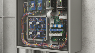
The internal architecture usually starts with a protected power supply. Fuses, circuit breakers, and transformers support safe voltage distribution. A central DDC controller processes input signals and executes control sequences. Input and output modules expand its capacity. Analog inputs may read a 0–10 V signal, while digital inputs detect contact status. Analog outputs modulate valves, and digital outputs operate relays or starters. Terminal blocks create orderly connections between field cables and modules. Clear labels matter during commissioning.

A communication interface links the panel with supervisory software or other controllers. Some panels also include network switches, gateways, and service ports. Components are commonly mounted on DIN rails inside a ventilated enclosure. Grounding, cable separation, and shielding reduce electrical noise. Small details often decide reliability. A neat drawing can still hide a poor termination. Field testing may reveal reversed polarity, missing feedback, or an incorrect sensor range. These faults are not dramatic, but they can distort the entire control strategy. Good technicians check live values, command responses, alarms, and wiring against the approved drawings. Safety interlocks should remain independent where required. The architecture may look simple, yet every terminal has a purpose.

What Is a DDC Panel in BMS? - Main Components and Internal Architecture

Architecture Layer Component or Module Primary Function Typical Inputs and Outputs Common Signal Type Design Considerations
Field Layer Temperature Sensor Measures air, water, duct, room, or equipment temperature for monitoring and control sequences. Supply-air temperature, return-air temperature, space temperature, chilled-water temperature. Resistance or analog voltage Sensor range and installation location should match the controlled application.
Field Layer Humidity Sensor Measures relative humidity to support ventilation, comfort, dehumidification, and condensation control. Indoor humidity, duct humidity, outdoor humidity. Analog voltage or current Duct mounting and airflow conditions can affect measurement accuracy.
Field Layer Pressure Sensor Measures differential or static pressure across filters, ducts, fans, pumps, or conditioned spaces. Filter pressure, duct static pressure, room pressure, water differential pressure. Analog voltage or current The selected pressure range should cover the expected operating conditions without excessive loss of resolution.
Field Layer Flow Sensor or Meter Determines airflow or fluid flow for balancing, energy monitoring, and equipment control. Airflow, chilled-water flow, heating-water flow, domestic-water flow. Pulse, analog, or network value Straight pipe or duct lengths may be needed for reliable flow measurement.
Field Layer Occupancy or Motion Sensor Provides occupancy information for demand-controlled ventilation, lighting control, and scheduling adjustments. Occupied state, motion detection, people count, zone status. Digital signal or network value Detection coverage and time delays should be configured for the space type.
Field Layer Actuator Moves dampers or valves in response to commands from the controller. Air damper position, chilled-water valve position, heating-valve position. Floating, analog, or network command Actuator torque, fail position, stroke time, and power requirements must be compatible with the final control element.
Field Layer Equipment Status and Safety Contact Reports operating status, alarms, interlocks, and safety conditions from field equipment. Fan proof, pump status, smoke alarm, freeze protection, high-pressure trip. Dry contact or digital input Safety circuits should remain effective even if the DDC controller or communication network is unavailable.
Control Layer DDC Controller Executes programmed control logic, compares measured values with setpoints, and generates commands. Sensor values, schedules, setpoints, alarms, equipment commands. Local I/O and network data Controller capacity should accommodate present requirements and reasonable future expansion.
Control Layer Universal Input Module Accepts configurable field signals from sensors, meters, and contacts. Temperature, humidity, pressure, current, voltage, resistance, dry contact. Configurable analog or digital input Input configuration must match the sensor type, signal range, and required engineering units.
Control Layer Digital Input Module Detects two-state conditions such as run status, alarm status, and safety trips. Open or closed contact, on or off status. Binary contact Input logic should define whether an open or closed circuit represents a normal condition.
Control Layer Analog Output Module Sends continuously variable commands to valves, dampers, drives, and other modulating devices. Valve position, damper position, fan-speed reference. Voltage or current The output range and minimum or maximum command limits should be coordinated with the controlled device.
Control Layer Digital Output Module Switches equipment or relays on and off according to control sequences. Fan start, pump start, heater enable, alarm relay. Relay or transistor output Output ratings and electrical isolation must suit the connected load or interposing relay.
Control Layer Control Program and Logic Applies schedules, interlocks, start-stop logic, reset strategies, proportional-integral control, and alarm rules. Setpoints, measured values, operating modes, enable commands. Software logic Sequences should include safe states, sensor failure responses, overrides, and restart behavior.
Power Layer Incoming Power Isolation Provides a means to disconnect electrical power from the panel for service and maintenance. Incoming supply to the control panel. AC power circuit The disconnecting means should be appropriately rated, accessible, and clearly identified.
Power Layer Circuit Protection Protects control circuits and connected equipment from overcurrent and short-circuit conditions. Controller supply, actuator supply, auxiliary circuits. Fuse or circuit breaker Protection ratings should be coordinated with conductor sizes, power supplies, and equipment fault levels.
Power Layer Control Power Transformer or Power Supply Converts incoming power to the low-voltage supply used by controllers, sensors, relays, and actuators. Low-voltage AC or DC control power. AC or DC power The capacity should include connected loads, inrush current, and an allowance for expansion.
Power Layer Relay and Interposing Relay Provides switching, isolation, signal multiplication, or electrical interface between controller outputs and equipment circuits. Start commands, enable signals, alarm contacts, interlocks. Coil and switched contact Relay contact ratings, coil voltage, suppression, and replacement access should be considered.
Communication Layer Field Network Interface Exchanges data between the DDC panel, distributed controllers, meters, variable-speed drives, and equipment controllers. Values, commands, alarms, schedules, operating modes. Digital communication Network topology, addressing, termination, and baud-rate settings must be consistent across the field network.
Communication Layer Building Automation Network Connection Links the local DDC controller to supervisory software, operator workstations, gateways, or other building systems. Trend data, alarms, graphics data, commands, system status. IP or serial communication Network security, access control, segmentation, and documentation are important for connected systems.
Panel Assembly Enclosure Protects internal electrical and control components from accidental contact and environmental conditions. Contains controller, terminals, power devices, relays, and wiring. Mechanical protection The enclosure should suit the installation environment, heat dissipation needs, and required ingress protection.
Panel Assembly Terminal Blocks Provide organized connection points for field wiring, power conductors, shields, and controller I/O. Sensor wiring, actuator wiring, contact wiring, network wiring. Screw, spring, or plug-in terminal Terminals should be labeled, grouped by function, and separated where voltage levels require segregation.
Panel Assembly DIN Rail and Wiring Duct Support modular components and keep internal wiring routed, protected, and serviceable. Mounting and routing infrastructure. Mechanical assembly Adequate spacing and separation reduce electromagnetic interference and simplify maintenance.
Panel Assembly Grounding and Shielding Arrangement Provides protective earthing and helps reduce electrical noise on sensitive control and communication circuits. Panel earth, cable shields, signal reference conductors. Protective and functional grounding Grounding practices should follow applicable electrical codes and the requirements of the control network.
Supervisory Layer Operator Interface Allows authorized personnel to view values, change setpoints, issue commands, acknowledge alarms, and review trends. Graphics, alarms, schedules, trends, overrides. Software interface User permissions and audit records help prevent unauthorized changes to operating parameters.
Supervisory Layer Alarm and Trend Functions Records abnormal conditions and historical operating data for diagnostics, verification, and energy analysis. High and low limits, equipment faults, temperature trends, runtime data. Digital records Alarm priorities, deadbands, time delays, sampling intervals, and data retention should be defined during commissioning.
Typical Control Sequence Air-Handling Unit Control Coordinates fan operation, temperature control, outdoor-air control, heating, cooling, and safety interlocks. Temperature, humidity, pressure, damper position, valve position, fan status. Mixed analog and digital signals Freeze protection, smoke control interfaces, and fan proof requirements should be addressed in the sequence of operation.
Typical Control Sequence Variable-Air-Volume Zone Control Maintains zone temperature and ventilation requirements by adjusting airflow and terminal-unit heating or cooling. Zone temperature, airflow, damper position, reheat command. Analog, digital, or network data Minimum airflow and occupancy-based ventilation settings should be coordinated with zone requirements.
Typical Control Sequence Plant Equipment Enable and Reset Stages or modulates pumps, chillers, boilers, or heat exchangers according to demand and operating conditions. Water temperature, flow, pressure, demand, equipment status. Analog, digital, or network data Lead-lag rotation, minimum run time, failure changeover, and setpoint reset strategies improve reliability and efficiency.

How a DDC Panel Controls Building Systems

What Is a DDC Panel in BMS?

A Direct Digital Control (DDC) panel is the working link between a building management system and its equipment. It receives signals from temperature, pressure, humidity, and occupancy sensors. Then, it processes programmed sequences and sends commands to valves, dampers, fans, pumps, and lighting relays. In a typical air-handling unit, the panel may compare room temperature with its setpoint. It can then adjust chilled-water flow or fan speed within seconds.

This control loop affects comfort, energy use, and equipment life. The International Energy Agency’s Buildings 2023 report states that buildings consume about 30% of global final energy. Better control cannot solve every inefficiency, but it can reduce unnecessary operation. U.S. Department of Energy guidance also identifies automated controls as a practical energy-saving measure in commercial buildings. Trends and alarms add another layer. Facility teams can spot a stuck damper, failed sensor, or simultaneous heating and cooling before occupants complain.

In practice, the sequence is rarely perfect. A drifting sensor can make a well-designed panel behave badly. That detail is easy to miss. A reliable commissioning process should test inputs, outputs, alarms, schedules, and failure responses. Technicians should also review trend logs after seasonal changes, not only during handover.

Tips: Label every field wire and point clearly. Keep setpoints documented. Test manual overrides, then return them to automatic control. Avoid changing several parameters at once; otherwise, the real cause may remain unclear.

Communication Protocols and Network Integration

What Is a DDC Panel in BMS?

A DDC panel is the field-level control center of a Building Management System. It reads temperature, pressure, humidity, and occupancy signals. Then, it adjusts valves, dampers, fans, and pumps. Its communication protocol decides how reliably those actions reach the supervisory workstation.

BACnet/IP commonly carries data across Ethernet networks. BACnet MS/TP uses twisted-pair wiring for controllers and sensors. Modbus RTU remains useful for meters and packaged equipment, while Modbus TCP operates through Ethernet. MQTT can support lightweight cloud messaging, but it needs careful topic design and security controls. Gateways translate between these protocols. They also introduce another failure point.

Network integration requires more than connecting cables. Engineers should define device addresses, point names, baud rates, object types, and alarm priorities. A dedicated automation VLAN can reduce unnecessary traffic. Network time synchronization improves trend accuracy. NIST SP 800-82 Rev. 3 stresses segmentation, controlled access, and secure remote maintenance for operational technology networks. These measures matter because the International Energy Agency reports that buildings consume about 30% of global final energy and produce around 26% of energy-related emissions.

Field commissioning reveals the truth. A damper may show “open” while remaining physically closed. A gateway may pass values but lose alarm states. I have seen clean graphics hide poor sensor placement. That is the uncomfortable part. DDC integration should include point-to-point testing, packet checks, trend reviews, and operator feedback. Protocol compatibility is only the beginning.

Installation, Maintenance, and Troubleshooting Considerations

A DDC panel in a building management system receives sensor data and controls equipment through programmed logic. Its installation affects every later maintenance task. Choose a dry, accessible location with enough clearance for wiring, testing, and future replacement. Keep power and communication cables separated where site conditions allow. Verify supply voltage, grounding, terminal torque, and controller addresses before energizing the panel. Record each point in an updated schedule. That record matters.

Maintenance should include visual inspections, alarm reviews, and trend checks at planned intervals. Look for loose terminals, heat marks, dust buildup, and condensation inside the enclosure. Compare sensor readings with a trusted handheld instrument, not only the software display. Back up programs before changes, then document who changed them and why. Battery replacement dates deserve attention. Small failures spread. A missed calibration can cause unstable temperatures, wasted energy, or uncomfortable rooms.

When equipment does not respond, check simple causes first: power, fuses, network continuity, and enable signals. Then compare live values with the point schedule and sequence of operation. A forced output may hide the real fault, so remove overrides after testing. If communication drops intermittently, inspect shielding, termination, and nearby electrical interference. Troubleshooting logs should include timestamps, measured values, and corrective actions. In practice, no checklist catches everything. Technicians should question unexpected readings instead of replacing controllers too quickly. That habit prevents repeat failures.